
Products
Options
Products
GHTS Series, pulser for the laboratory use.
| Switch Model | Max. Voltage (kV) | Peak Current (A) | HV Pulse Width (ns) | Housing Dimensions (mm3 ) | Datasheet |
| GHTS 30 | 2 x 3 | 2 x 30 | 100…∞ | 170 x 110 x 45 | |
| GHTS 30 A | 2 x 3 | 2 x 60 | 100…∞ | 170 x 110 x 45 | |
| GHTS 60 | 2 x 6 | 2 x 15 | 100…∞ | 170 x 110 x 45 | |
| GHTS 60 A | 2 x 6 | 2 x 30 | 100…∞ | 210 x 110 x 45 | |
| GHTS 60 B | 2 x 6 | 2 x 60 | 100…∞ | 210 x 110 x 45 | |
| GHTS 100 | 2 x 10 | 2 x 15 | 100…∞ | 210 x 110 x 45 | |
| GHTS 100 A | 2 x 10 | 2 x 30 | 100…∞ | 210 x 110 x 45 |
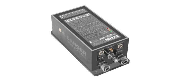
FSWP Series, Fast Square Wave Pulser, for system integration.
| Switch Model | Max. Voltage (kV) | Peak Current (A) | HV Pulse Width (ns) | Housing Dimensions (mm3 ) | Datasheet |
| FSWP 51-02 | 5.4 | 25 | 50 ns…∞ | 175 x 80 x 45 | |
| FSWP 71-02 | 7.2 | 20 | 50 ns…∞ | 175 x 80 x 45 | |
| FSWP 91-01 | 9 | 15 | 50 ns…∞ | 175 x 80 x 45 |
FQD Series, Fast Q-Switch Pockels Cell Driver, for system integration.
| Switch Model | Max. Voltage (kV) | Peak Current (A) | HV Pulse Width (ns) | Housing Dimensions (mm3 ) | Datasheet |
| FQD-30-04-C | 3 | 40 | 100 ns…1 ms | 64 x 30 x 18 | |
| FQD 30-08-UF | 3 | 80 | 100 ns…1 ms | 79 x 38 x 19 | |
| FQD 30-06-UF | 3.6 | 60 | 100 ns…1 ms | 79 x 38 x 19 | |
| FQD-40-02-C | 4 | 20 | 100 ns…1 ms | 64 x 30 x 18 | |
| FQD-40-03-C | 4 | 30 | 100 ns…1 ms | 64 x 30 x 18 | |
| FQD 40-03 | 4 | 35 | 100 ns…1 ms | 79 x 38 x 19 | |
| FQD 40-06 | 4 | 60 | 100 ns…1 ms | 79 x 38 x 19 | |
| FQD-50-02-C | 5 | 20 | 100 ns…1 ms | 64 x 30 x 18 | |
| FQD 50-02 | 5 | 25 | 100 ns…1 ms | 79 x 38 x 19 | |
| FQD 50-05 | 5 | 50 | 100 ns…1 ms | 79 x 38 x 19 | |
| FQD 60-02 | 6 | 20 | 100 ns…1 ms | 79 x 38 x 19 | |
| FQD-60-03-C | 6 | 30 | 100 ns…1 ms | 64 x 30 x 18 | |
| FQD 60-04 | 6 | 40 | 100 ns…1 ms | 79 x 38 x 19 | |
| FQD 80-01 | 8 | 15 | 100 ns…1 ms | 79 x 38 x 19 | |
| FQD-80-02-C | 8 | 25 | 100 ns…1 ms | 64 x 30 x 18 | |
| FQD 80-03 | 8 | 30 | 100 ns…1 ms | 79 x 38 x 19 |
DSM Series, Differential Switch Mode Pulser, for system integration.
| Switch Model | Max. Voltage (kV) | Peak Current (A) | HV Pulse Width (ns) | Housing Dimensions (mm3 ) | Datasheet |
| DSM 31-03 | 3 | 30 | 4 ns – ∞ | 102 x 76 x 20 | |
| DSM 31-02 | 3.6 | 25 | 5 ns – ∞ | 102 x 76 x 20 | |
| DSM 61-01 | 6 | 15 | 5 ns – ∞ | 102 x 76 x 20 | |
| DSM 91-01 | 9 | 12 | 10 ns – ∞ | 102 x 76 x 20 |
FHPP Series, Fast High-Voltage Precision Pulser.
| Switch Model | Max. Voltage (kV) | Peak Current (A) | HV Pulse Width (ns) | Housing Dimensions (mm3 ) | Datasheet |
| FHPP 60 | 2 x 6 | 2 x 80 | 60…∞ | 184 x 105 x 92 | |
| FHPP 80 | 2 x 8 | 2 x 60 | 60…∞ | 184 x 105 x 92 | |
| FHPP 100 | 2 x 10 | 2 x 50 | 60…∞ | 184 x 105 x 92 | |
| FHPP 120 | 2 x 12 | 2 x 30 | 60…∞ | 184 x 105 x 92 |
Options
Options for the GHTS series:
| Options | Description |
| Option 01 | Protective Series Resistor 200 Ohm. |
| Option 02 | Built-in Miniature Fan |
| Option 03 | Improved thermal conductivity of the internal switching module by means of an internal ceramic cooling surface |
Options for the FSWP Series:
| Options | Description |
| ALL-OFF | “Voltage free pulse output in case of fault or if inhibit is “”L””. Suggested in circuits with positive and negative supply. A pull down-resistor may be required to keep the opened switches potential-free. ” |
| FL-IN | Floating High Voltage Inputs |
| I-PC | Integrated Part Components: Integration of small part components according to customer’s specifications (e.g. buffer capacitors |
| UL94 | Flame Retardant Casting Resin: Casting resin according to UL-94-VO. Minimum order quantity required. (2) |
| CF-LC | Copper Cooling Fins for liquid cooling: Double fins |
| CCF | Ceramic Cooling Flange: Bottom side of switching module made of a plano grinded ceramic plate. Integrated metal frame for uniform and safe contact pressure. Max. 40 kVDC isolation. |
| C-DR | Cooling for Driver: Extra cooling for the driver and control electronics. Recommended in combination with option HFS at higher switching frequencies. (2) |
| ILC | Indirect Liquid Cooling: Liquid cooling for all kind of conductive coolants incl. water. Internal heat exchanger made of ceramics. For medium power dissipation. |
| DLC | Direct Liquid Cooling: Internal cooling channels arround the power semiconductors. The most efficient cooling for high frequency applications. Non-conductive coolants only. |
Options for the FQD Series:
| Options | Description |
| HFS | High Frequency Switching: External supply of auxiliary driver voltage. Necessary if the specified “Max. Operating Frequency” shall be exceeded. (2) |
| I-PC | Integrated Part Components: Integration of small part components according to customer’s specifications (e.g. buffer capacitors |
| PT-C | Pigtail for Control Connection: Flexible leads (l=75 mm) with PCB connector. This option is only relevant for switching modules with pins. |
| PIN-C | Pins for Control Connection: Gold plated pins for printed circuit board designs (special sockets available). Only relevant for switching modules which have pigtails as standard. |
| UL94 | Flame Retardant Casting Resin: Casting resin according to UL-94-VO. Minimum order quantity required. (2) |
| TH | Tubular Housing: Tubular instead of rectangular housing. Adaption to specific ambient conditions or in case of difficult assembly situations. (2) |
| FC | Flat Case: Height of standard plastic housings reduced to 19 mm or less. Not in combination with cooling options CF |
| ITC | Increased Thermal Conductivity: Special moulding process to increase the thermal conductivity of the module. Pd(max) will be increased by approx. 20-30%. (2) |
| CF | Copper Cooling Fins d = 0.5 mm: Fin height 35 mm. Nickel plated. For air cooling with forced or natural convection as well as for liquid cooling with non-conductive coolants. |
| CF-1 | Copper Cooling Fins d = 1 mm: Fin thickness 1.0 mm instead of 0.5 mm. The Max. Power Dissipation Pd(max) will be increased by ~80 %. For air or liquid cooling (e.g. Galden® or oil). |
| CF-X2 | “Copper Cooling Fins “”XL””: Fin area enlarged by factor 2. Recommended for natural air convection. No significant cooling power improvement in connection with forced air or liquid cooling.” |
| CF-X3 | “Copper Cooling Fins “”XXL””: Fin area enlarged by factor 3. Recommended for natural air convection. No significant cooling power improvement in connection with forced air or liquid cooling.” |
| CF-CS | Copper Cooling Fins with customized shape: Individual shape to meet specific OEM requirements. (2) Can be combined with options CF-1 |
| CF-LC | Copper Cooling Fins for liquid cooling: Double fins |
| CF-D | Double Copper Cooling Fins: Approx. 100% more cooling power |
| CF-S | Copper Cooling Fins: Semiconductors soldered on fins. Approx. 30% to 100% more cooling power (type depending). Combinable with options CF-D |
| CF-GRA | Non-isolated Cooling Fins made of graphite: Very light weight compared to copper at similar heat transfer |
| CF-CER | Isolated Cooling Fins made of ceramics: Heat transfer properties similar to alumina. Forced convection recommended due to 2 mm spacing between fins. Height 35 mm. |
| CCS | Ceramic Cooling Surface: Top side of switching module made of ceramics. Heat transfer properties similar to alumina. Max. 20 kVDC isolation. Forced convection recommended. |
| CCF | Ceramic Cooling Flange: Bottom side of switching module made of a plano grinded ceramic plate. Integrated metal frame for uniform and safe contact pressure. Max. 40 kVDC isolation. |
| C-DR | Cooling for Driver: Extra cooling for the driver and control electronics. Recommended in combination with option HFS at higher switching frequencies. (2) |
| GCF | Grounded Cooling Flange: Nickel-plated copper flange for medium power. Max. isolation voltage 40kV. Increased coupling capacitance CC. |
| GCF-X2 | Grounded Cooling Flange |
| ILC | Indirect Liquid Cooling: Liquid cooling for all kind of conductive coolants incl. water. Internal heat exchanger made of ceramics. For medium power dissipation. |
| DLC | Direct Liquid Cooling: Internal cooling channels arround the power semiconductors. The most efficient cooling for high frequency applications. Non-conductive coolants only. |
| HI-REL | High Reliability / MIL Versions: Available on request. (2) |
Options for the DSM Series:
| Options | Description |
| HFS | High Frequency Switching: External supply of auxiliary driver voltage. Necessary if the specified “Max. Operating Frequency” shall be exceeded. (2) |
| I-PC | Integrated Part Components: Integration of small part components according to customer’s specifications (e.g. buffer capacitors |
| PT-C | Pigtail for Control Connection: Flexible leads (l=75 mm) with PCB connector. This option is only relevant for switching modules with pins. |
| PIN-C | Pins for Control Connection: Gold plated pins for printed circuit board designs (special sockets available). Only relevant for switching modules which have pigtails as standard. |
| UL94 | Flame Retardant Casting Resin: Casting resin according to UL-94-VO. Minimum order quantity required. (2) |
| TH | Tubular Housing: Tubular instead of rectangular housing. Adaption to specific ambient conditions or in case of difficult assembly situations. (2) |
| FC | Flat Case: Height of standard plastic housings reduced to 19 mm or less. Not in combination with cooling options CF |
| ITC | Increased Thermal Conductivity: Special moulding process to increase the thermal conductivity of the module. Pd(max) will be increased by approx. 20-30%. (2) |
| CF | Copper Cooling Fins d = 0.5 mm: Fin height 35 mm. Nickel plated. For air cooling with forced or natural convection as well as for liquid cooling with non-conductive coolants. |
| CF-1 | Copper Cooling Fins d = 1 mm: Fin thickness 1.0 mm instead of 0.5 mm. The Max. Power Dissipation Pd(max) will be increased by ~80 %. For air or liquid cooling (e.g. Galden® or oil). |
| CF-X2 | “Copper Cooling Fins “”XL””: Fin area enlarged by factor 2. Recommended for natural air convection. No significant cooling power improvement in connection with forced air or liquid cooling.” |
| CF-X3 | “Copper Cooling Fins “”XXL””: Fin area enlarged by factor 3. Recommended for natural air convection. No significant cooling power improvement in connection with forced air or liquid cooling.” |
| CF-CS | Copper Cooling Fins with customized shape: Individual shape to meet specific OEM requirements. (2) Can be combined with options CF-1 |
| CF-LC | Copper Cooling Fins for liquid cooling: Double fins |
| CF-D | Double Copper Cooling Fins: Approx. 100% more cooling power |
| CF-S | Copper Cooling Fins: Semiconductors soldered on fins. Approx. 30% to 100% more cooling power (type depending). Combinable with options CF-D |
| CF-GRA | Non-isolated Cooling Fins made of graphite: Very light weight compared to copper at similar heat transfer |
| CF-CER | Isolated Cooling Fins made of ceramics: Heat transfer properties similar to alumina. Forced convection recommended due to 2 mm spacing between fins. Height 35 mm. |
| CCS | Ceramic Cooling Surface: Top side of switching module made of ceramics. Heat transfer properties similar to alumina. Max. 20 kVDC isolation. Forced convection recommended. |
| CCF | Ceramic Cooling Flange: Bottom side of switching module made of a plano grinded ceramic plate. Integrated metal frame for uniform and safe contact pressure. Max. 40 kVDC isolation. |
| C-DR | Cooling for Driver: Extra cooling for the driver and control electronics. Recommended in combination with option HFS at higher switching frequencies. (2) |
| GCF | Grounded Cooling Flange: Nickel-plated copper flange for medium power. Max. isolation voltage 40kV. Increased coupling capacitance CC. |
| GCF-X2 | Grounded Cooling Flange |
| ILC | Indirect Liquid Cooling: Liquid cooling for all kind of conductive coolants incl. water. Internal heat exchanger made of ceramics. For medium power dissipation. |
| DLC | Direct Liquid Cooling: Internal cooling channels arround the power semiconductors. The most efficient cooling for high frequency applications. Non-conductive coolants only. |
| HI-REL | High Reliability / MIL Versions: Available on request. (2) |
| [1] | New option code: Data sheets may differ from this coding system (especially older ones) and do not indicate all possible options as per above table. |
| [2] | Please consult factory for detailed information. |
| [3] | These options are EMC-relevant and are recommended for industrial power applications |